
Vehicle Counting Using Double Virtual Lines
Published:
This summer, I have an opportunity of a 3-month internship in Multimedia Research Center, University of Alberta.
This post is a summary of my work in the first two weeks. I finished a primary project based on the paper Vehicle Counting Based On Double Virtual Lines.
You can get a PDF version of this report from here.
You can get the source code on my Github.
Contents
Part I Overview of the author’s work
1.1 Motivation
- Traditionally, virtual loops are assigned for counting vehicles. However, this will not function properly when vehicles are roadway departure due to overtaking or crossing (e.g. repeat counting may occur if one vehicle is detected by virtual loops on different lanes).
Solution: assign Double Virtual Lines (DVL) - After the background subtraction operation, we get a binary image of foreground objects (the vehicles). However, it usually happens that one target is splited into many fragments, and many targets are merged into one block (refer to Figure 1.1), which may cause false counting. This problem is described as ‘mapping of one to many or many to one’.
Solution: dual template convolution

Figure 1.1
One target may split into many fragments.
Two targets may tend to merge into one block.
1.2 Framework of the proposed method
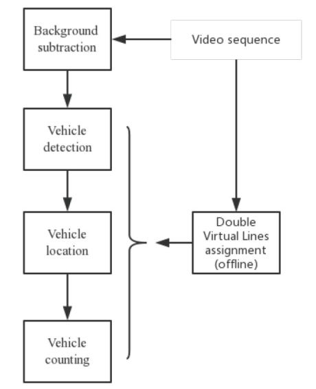
Figure 1.2 block diagram of the proposed method
1.2.1 DVL assignment
The DVL is assigned by estimating the vehicle’s 2-D projection on the image plane. The projective transformation matrix is needed. Refer to the paper for more details.
Let L donate the width of DVL. In my own experiment, L is 100. According to the author, it is the case that the DVL nearly covers the vehicle (refer to figure 1.1).
1.2.2 Background subtraction
The author uses Mixture of Gaussians (MOG) method to model the background. The foreground targets can be computed by
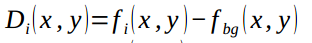
Where fi(x,y) is the ith frame, and fbg(x,y) is the background model of the frame.
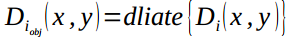
1.2.3 Vehicle detection
Di(x,y) is already the mask of foreground targets. Morphological filtering is used to remove the holes and enhance the targets. Dilation operation with a disk-shaped structuring element is used.
The result is shown in figure 1.3.
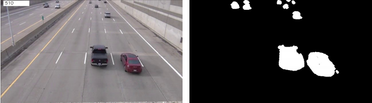
Figure 1.3
left: original image (frame # 510)
right: foreground targets
1.2.4 Vehicle location
Dual template convolution is used to solve the problem mentioned as ‘mapping of one to many or many to one’ (chapter 1.1).
1.mapping of one to many
The first template, which is a matrix filled with 1’s, is designed to deal with the mapping of one to many. Let tmp1 donate the first template.
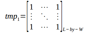
Where L is the width of double virtual lines. In my experiment, W=50, L=100.
The convolution operation is performed only in the detection zone, i.e. between the DVL (refer to figure 1.4).
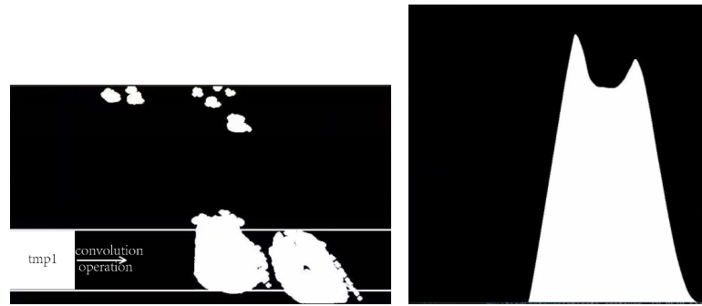
Figure 1.4
right: diagram of 1st template convolutional operation
left: diagram of convolution curve
After the convolution operation, we can see that the peaks of the curve indicate the candidate targets. This distinguishes the two nearby vehicles, thus deals with the mapping of one to many.
2.mapping of many to one
The second template is designed to detect holes within the target area. I found that this operation is unnecessary because of the following two reasons.
- The holes can be eliminated as long as the background subtraction method is robust enough, and morphological filtering is appropriately used.
- Even if there do exist some tiny holes within the target area (which may give rise to ‘false peak’ in the convolution curve), their influence can be fully eliminated by properly designed counting rules.
1.2.5 Vehicle counting
After vehicle location, each peak may indicate a vehicle in the detection zone. However, in order to overcome repeat counting and inaccurate counting, effective counting rules are needed. The peak is kept as a vehicle only if it satisfies all the following rules; otherwise, it is deleted from candidate peaks.
- Rule #1 Large peak value: the peak value corresponding to the target should be larger than the threshold (T_s). This is designed to rule out the influence of noise.
- Rule #2 Keeping horizontal safety space: the distance between two neighboring peaks should be larger than the threshold (T_HDist).
- Rule #3 Keeping vertical safety space: the distance between any of the two peaks in two consecutive frames should be larger than the threshold (T_VDist), i.e. if in two consecutive frames, there are peaks that are too close to each other, they should indicate the same vehicle (which remains in the detection zone for several frames). Clearly, this rule is designed to eliminate repeat counting.
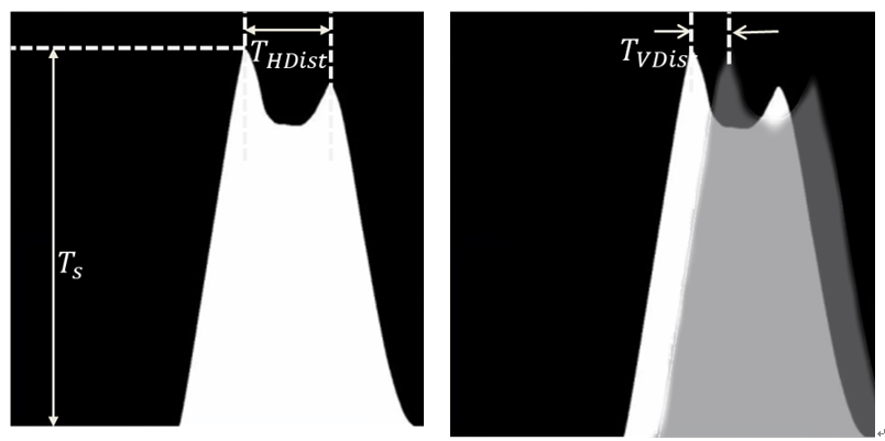
Figure 1.5 Counting rules
Part II My implementation and experiment
2.1 Test video
The author gives the link to the dataset they used. Sadly, it cannot be reached now. I’ve sent an email to the author but got no reply yet. Therefore, I use one video found from the Internet for the test of my code. Figure 2.1 shows one frame of it.
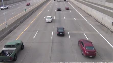
Figure 2.1 one frame of the test video
2.2 Parameters
Due to the difference of the test video, I have to set the values of parameters myself. The values are shown below. Note that the convolution curve has been normalized to scale [0,1].
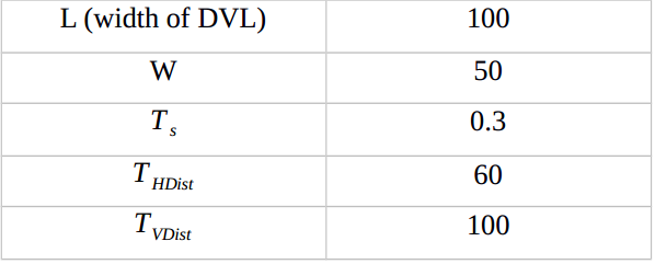
Table 2.1 values of the parameters
2.3 Result
2.3.1 Why Rule #1 works
I record some of the results of frame #87 to show the effectiveness of Counting Rule # 1. Refer to Figure 2.2.
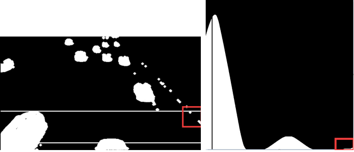
Figure 2.2 Foreground targets & convolution curve of frame #87
In the left image, there is some noise within the detection zone (red rectangle region). It causes one tiny ‘peak’ in the corresponding convolution curve (red rectangle region in the right image). Without Counting Rule #1, this would be falsely detected and counted.
2.3.2 Why Rule #2 & #3 work
I record four consecutive frames to show the effectiveness of Counting Rule # 2 & #3. Refer to Figure 2.2.
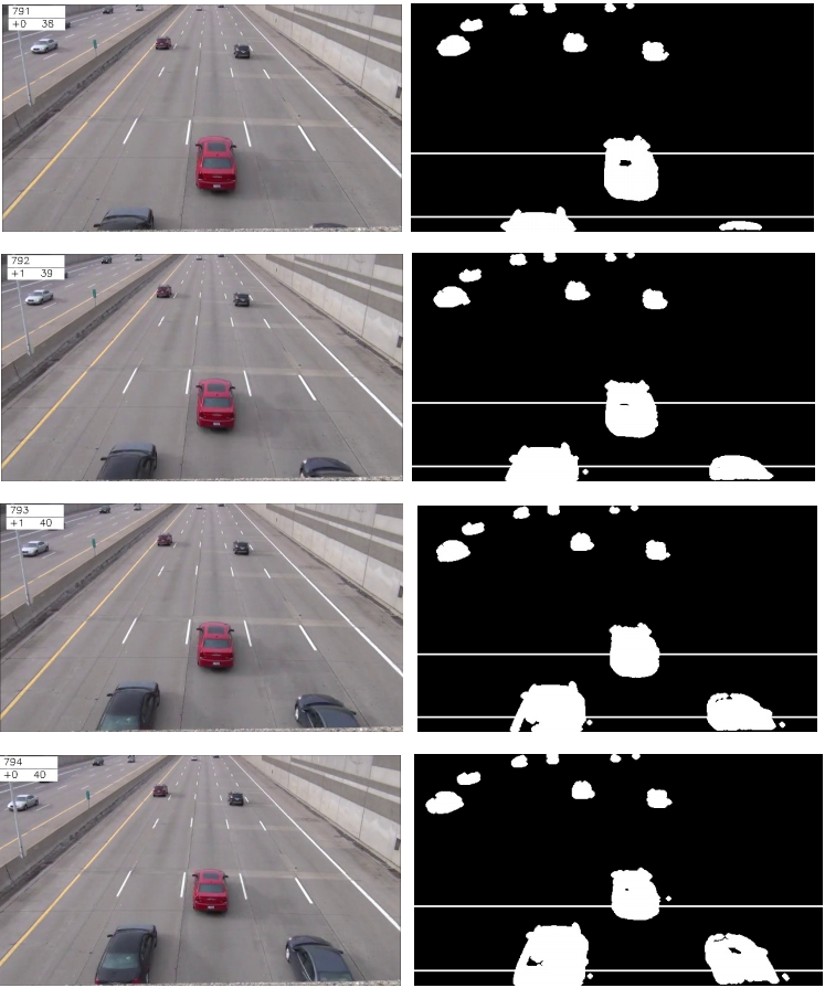
Figure 2.3 Four consecutive frames
left column: origin image
right: foreground targets with the detection zone
In each image in the left column, there are three numbers shown on the top-left corner (e.g. in the first image they are 791, +0, 38). The first number is the current frame number. The second number is the number of the newly counted target. The third number is the current total number of counted targets.
In frame #791, the red car in the center is the 38th one. In frame #792, the car on the left side of the red one is detected and counted. In frame #793, the one on the right side is counted. Note that because of Rule #2 and #3, repeat counting of the left one is prevented. In frame #794, there are no newly detected targets. Again, repeat counting is eliminated.
Part III Future work
3.1 Current problems
- To many manually assigned parameters
Parameters such as W, L, T_s, T_HDist, T_VDist need to be assigned manually. The values are greatly influenced by the changing of lanes, viewing perspective, environment, etc. Therefore, it will be disturbing to port the system to a new environment. - This is a pipeline method
In a pipeline framework, the robustness of the latter module depends largely on the former one. What’s more, each module has its own parameters. This makes it difficult to debug the system.
3.2 Possible means of improvement
3.2.1 Means of improvement
Deep learning method has seen heavy use in the field of computer vision. Deep learning models learn parameters themselves, and they allow end-to-end training. I consider combining CNN and RNN to improve the author’s work. Refer to figure 3.1.
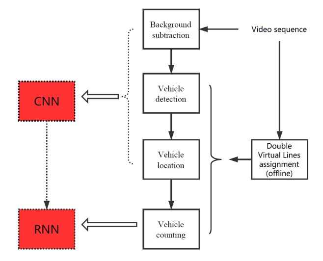
Figure 3.1 Possible means of improving the author’s work.
- Use CNN to locate the foreground targets and extract features from each frame of the work. Several papers have proposed CNN models for background subtraction ([2,3]). Inspired by this, I consider using CNN to detect foreground targets.
- Accurate vehicle counting requires not only information from one single frame, but the relation between several consecutive frames. RNN is powerful in modeling sequential data like that.
- As for the combination of CNN and RNN, a model called convolutional recurrent neural network (CRNN) has been used in several papers. [4,5] are two paper that may help.
3.2.2 Potential challenges
- I’ve been familiar with CNN and its implementation using Tensorflow. But I only know about basic ideas of RNN. It may take me some time to propose and implement the model.
- Deep learning methods require large training data. Fine-tuning classical models can be a good start, but data is still essential.
Reference
[1] Xu H, Zhou W, Zhu J, Huang X, and Wang W. Vehicle counting based on double virtual lines. Signal, Image and Video Processing. 2017 Jul 1;11(5):905-12
[2] Mohammadreza Babaee, Duc Tung Dinh, and Gerhard Rigoll. A Deep Convolutional Neural Network for Background Subtraction. arXiv:1702.01731v1 [cv.CV]
[3] Marc Braham and Marc Van Droogenbroeck. Deep Background Subtraction with Scene-Specific Convolutional Neural Networks. 2016 International Conference on Systems, Signals and Image Processing (IWSSIP)
[4] Pedro Pinheiro, and Ronan Collobert. Recurrent Convolutional Neural Networks for Scene Labeling. Proceedings of the 31st International Conference on Machine Learning, PMLR 32(1):82-90, 2014
[5] Hao Wu and Saurabh Prasad. Convolutional Recurrent Neural Networks for Hyperspectral Data Classification. Remote Sensing, 2017, 9(3): 1-20